ESP8266 Temperature plotting iot
Table of contents
Introduction
This project makes it possible to monitor temperature readings from a number of sensors simultaneously.
It’s installed in my parents home to be able to follow how hot water is produced, for knowing when to burn more wood, and for checking how their water heating solar panels are doing during the summers.
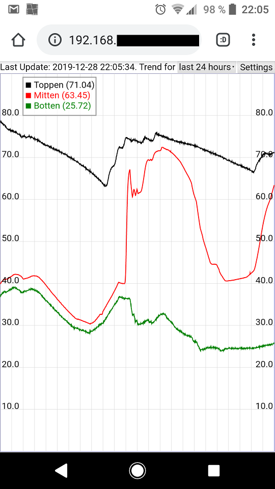
The captured curve below show three readings in °C from their hot water storage tank (top, middle, and bottom). During that period of time, we got a cold period with outside temperatures of -18.5°C (-1.3°F).
The middle and bottom readings in the tank get very close to each other when the shunt valve is fully closed, and all radiators in the house are cooling the water in the tank as much as possible. Interestingly, the temperature in the middle made a huge jump after keeping a fire lit for about two hours.
Repositories
There are two different repositories for this project:
Software portion: https://github.com/optisimon/esp8266_temperature_iot
Hardware portion: https://github.com/optisimon/esp8266_temperature_iot_PCB
Reason for split is that many people might just want to connect one-wire sensors to the project. Then they can just breadboard it, and won’t need the analog circuitry on the PCB.
Software
The frontend is basically a small temperature plotting html page.
A static web page is served to anyone connecting. A bit of javascript periodically request a json object containing all values for the curves to plot, and a html canvas element is used for actually drawing the data.
The user can choose between a plot containing readings from the last 24 hours, or a plot for the last hour.
The web interface also allows renaming all sensors arbitrarily, selection of which sensors to store / plot, as well as allows changing network settings:
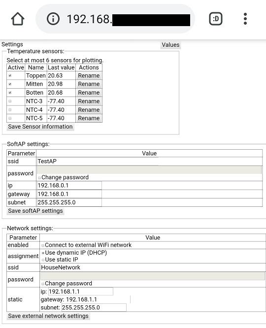
It can be accessed wirelessly over WiFi as it’s pretending to be an access point (with some limitations, such as not allowing more than four clients connected simultaneously). The software can optionally also connect to another WiFi network to make itself accessible there. (Make sure its pretended access point IP and the other network don’t have overlapping IP address ranges. That don’t seem to be supported at all by the ESP8266 network stack).
The software provides an external api which is well documented and straight forward to use.
Sampling temperatures
Converting sampled NTC thermistor values into temperatures turned out to be quite interesting. The hardware is simple, just a voltage divider between a 10 kOhm precision resistor and the sensing NTC thermistor. I threw in some additional ESD protection and some smoothing capacitors just for good measure. Adafruit have a really good walk through of the theory behind converting sampled readings into temperatures. The thing I hadn’t realized before was that by using an ADC accepting an external voltage reference we don’t need to know which voltage we supply to the voltage divider.
Sampling values using the MCP3208 ADC was also slightly interesting since it would typically require low impedance sources, while an NTC thermistor in a voltage divider configuration is far from that. The problem is the sample and hold procedure inside that ADC. You have a very short time to charge the hold capacitor, and a high impedance source would not be able to do that. At the same time, I didn’t want to add additional circuitry doing that. The solution I choose was to add input capacitors across all inputs, as well as increasing the sample and hold time by bitbanging the SPI transactions. That allowed us to stretch out the sample and hold operation for an arbitrary extended time period, while running the rest of the transactions fast. With a 1MHz SPI clock, the default sample window would have been 1.5 us (1.5 clock cycles).
By bitbanging and throwing in some additional sleeps where appropriate, the sampling window was extended from 1.5 us to 8.0 us at which point I didn’t see any issues with too low ADC readings.
While bitbanging, the overhead of the arduino library became excessively clear. Reading the source code one could think that the sampling window is just 3 us (when assuming that an 80MHz MCU frequency makes everything except the delays negligible). But in reality they do take 8 us when measured with an oscilloscope. This is also possibly dangerous, since a newer better optimized version of the compiler and/or arduino toolchain could possibly talk too fast to the ADC.
Hardware
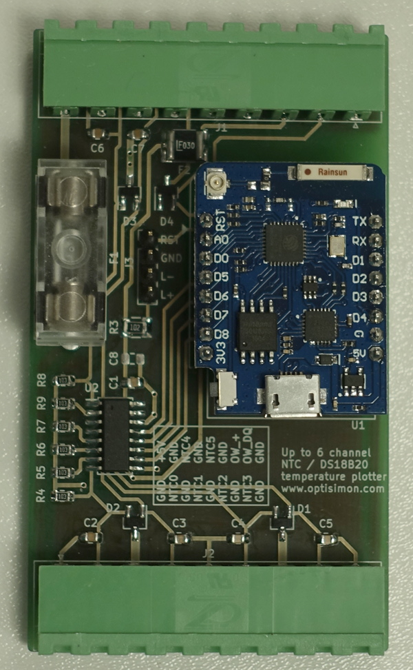
Current hardware consist of a custom PCB with a MCP3208 ADC and a Wemos D1 mini pro v1.0.0 ESP8266 module. Unfortunately, the newest revision (v2.0.0 when I wrote this) of that module have a different form factor, and I don’t know if it would fit inside the DIN enclosure I used.
Up to 6 NTC sensors can be attached directly to the PCB. Digital one wire temperature sensors (DS18B20) could also be used, but there is currently an artificial software limit preventing storing/plotting more than 6 curves at once.
Schematic and PCB layout (kicad design files as well as pdf / gerber files) are available at: https://github.com/optisimon/esp8266_temperature_iot_PCB
Finished assembled PCB turned out like this:
And the PCB combined with a DIN enclosure made a nice looking combination:
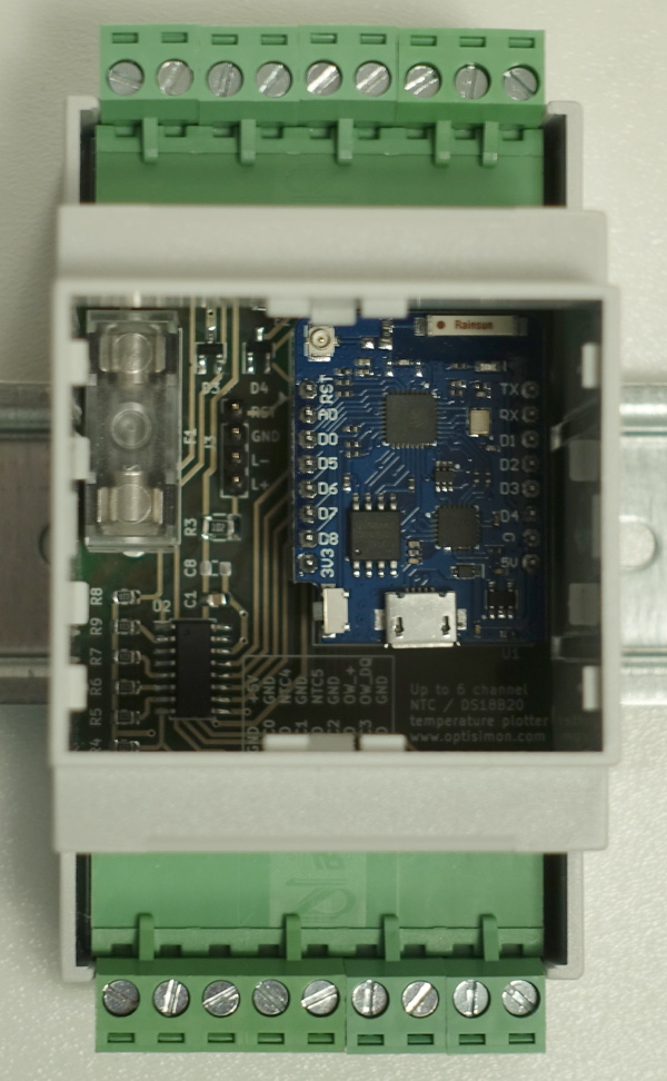
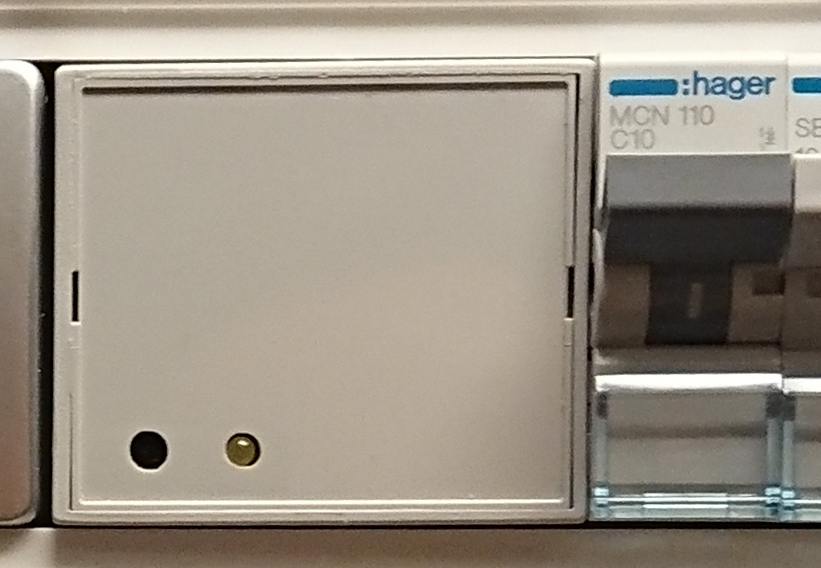
Although you’ll only see a blank front face on the DIN enclosure unless you like me use a breadbord to add a status LED as well as a reset button to the front (a pin header is provided for that on the PCB):
Someone might find the actual list of odd bits and pieces in the project useful, since thats usually something you have to order and verify before designing the PCB.
| Article | Store | Description |
|---|---|---|
| Axxatronic CNMB-3-KIT-CON | conrad.com | DIN rail enclosure |
| Mean Well HDR-15-5 | conrad.com | 5V DIN rail power supply |
| RND 205-00206 | elfa.se | angled PCB pin header for connecting connectors |
| RND 205-00177, RND 205-00178, RND 205-00179, RND 205-00180 | elfa.se | a few screw connectors usable with the above pin header |
| MCP3208-CI/SL | elfa.se | A/D converter, SO-16, 12bit, 8 channel |
| PESD3V3L2BT,215 | elfa.se | Bidirectional ESD protection diode, 3.3V, SOT-23 (might not be really needed) |
| Schurter 0031.8201 | elfa.se | Fuse holder |
| Schurter 0853.0551 | elfa.se | Fuse holder cover (not needed, just looks nice) |
| 2016L030DR | elfa.se | Polyfuse, sustains 0.3A, but trips @ 0.6A (not what I thought I ordered, see polyfuse rating below ) |
Improvement considerations
A collection of improvement ideas I would consider if I would redo this project.
Noise
I got more noise in the readings when the system was installed in their garage, most likely since the temperature probe wires was bundled together with a lot of live wires for up to 4 meters. I had tested it before without noticing noise but then the cables was only parallell to 240V wires with purely resistive loads for about 2 meters, and not zip tied together with wires going to motors. All my readings used to look like the red curve.
Possible workarounds would be to increase the capacitors at the inputs to the AD converter, or to sample multiple times and average, to use shielded cables, or to separate sensors from live wires. The noise is not severe enough for me to take any immediate action.
Polyfuse rating
The polyfuse for the one wire connection was not sized correctly. Its trip point turned out to be 600mA instead of a more reasonable 300mA which I assumed from the listing I sourced the component from. The voltage regulator on my D1 mini pro v1.0.0 board can start to go into current limiting mode above 500mA (or typically at 600mA), so you would loose the last 24 hours of data if you short circuit the 3.3V line dedicated for one wire sensors to ground.
The workarounds could be as simple as not using a polyfuse (just add a jumper wire), avoiding short circuiting that terminal, only using parasitic power (i.e. simply not connecting anything there), or adding a separate 5V to 3.3V regulator for the onewire interface. I decided to mount the polyfuse anyway, hoping it might protect the fast glass fuse rated at 1A, since that one might be a pain to change.
Self heating
A known possible problem with NTC temperature sensors are that they heat up slightly when you apply a voltage across them. I found that to be negligible in my use case, and dropped the idea of switching off the voltage to them between each time I make a reading.
Embeddedness
The code could be rewritten to as much as possible prevent use of dynamic memory allocations, in case that would lead to fragmented memory and a system that would reboot or hang after a period of uptime. I’ve tested for an hour or two to continuously request the large 24h json blob from three different concurrent loops without crashing. Since we could tolerate ocassional crashes in our system, I decided to keep it as-is.
Temperature to text conversion
I sped up the temperature to text conversion (and cut storage requirements by half) by storing the temperature as a 16 bit integer (after multiplying by 100) instead of as a float. It might be better to use some custom BCD:ish encoding to speed up the conversion even more. At most we store a sensor every 10’th second, but when reading the sensors over the api, thousands of sensor values are converted to a text representation, and it might be possible to do that even faster.
PCB mounting holes
It would have been easy to layout the PCB to allow mounting the PCB to almost anything using four mounting studs. That would have made it more generally useful, than just designing it for being mounted in a specific DIN rail enclosure.