RPM Revolution Meter using microphone input and a reflex detector
Table of contents
- Table of contents
- Introduction
- The microphone input of modern computers
- Required hardware
- The software
- Useful software libraries
Introduction
Interested in an application measuring rotation speed using minimal external hardware?
We can do that by hooking a few components to the mic input of a computer, and analyze the audio input.
The microphone input of modern computers
Microphone inputs on computers and laptops typically provide a small and current limited voltage to the mic connector. The laptops I’ve tested provides between 2.3 to 2.9 V to the RING of the connector (but be prepared for up to 5V). I think all of the ones in the list below gave the same voltage to both the tip and the ring (i.e. they do support stereo microphones).
For historical reasons, I decided to use only the RING for power and only the TIP for signal return. Really old soundcards used to provide 5V in series with 2.2 kOhm to the RING, and took the input signal from the TIP.
| Computer | RING Voltage (no load) | RING Voltage (1.2 kOhm load) | Current (1.2 kOhm load) | Internal resistance (estimated) |
|---|---|---|---|---|
| HP laptop | 2.9 V | 1.0 V | 0.83 mA | 2.3 kOhm |
| Sony laptop | 2.3 V | 0.3 V | 0.25 mA | 8.0 kOhm |
| Stationary (front) | 2.6 V | 0.65 V | 0.54 mA | 3.6 kOhm |
| H4n (ext mic) | 2.9 V | 1.0 V | 0.83 mA | 2.3 kOhm |
It’s evident that we can’t draw a lot of current. But as long as the open circuit voltage is higher than the forward voltage of our LED, we would be able to send out light (Vforward is around 1.2 V in this case). And since the microphone input is extremely sensitive, it’s perfect for picking up the small signal we’ll get back.
Required hardware
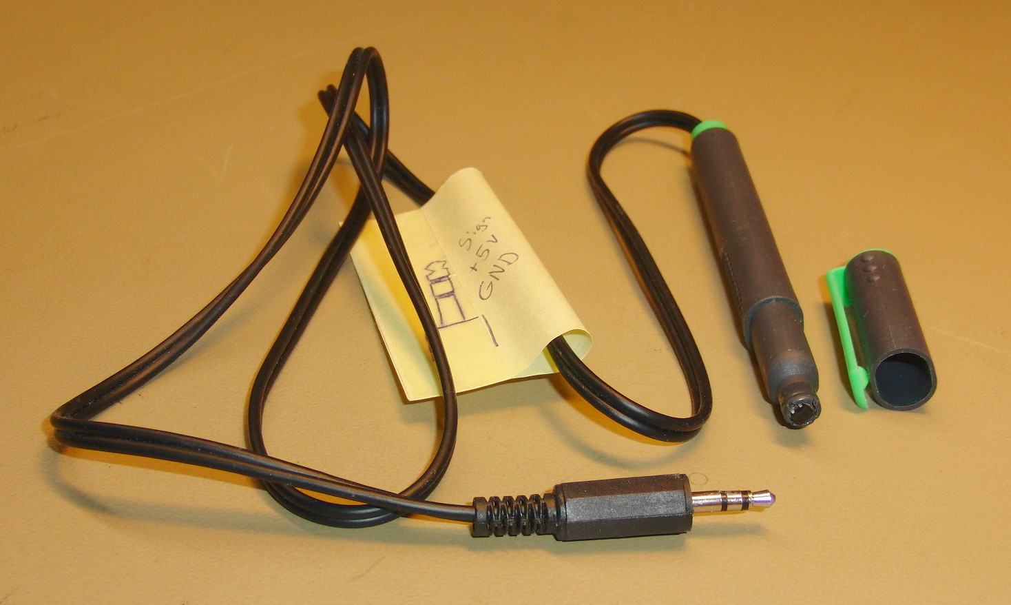
The circuit below have worked with all the computers I’ve had at hand, and will provide an audio signal back over the mic input showing what’s happening in front of the reflex detector. Note that these mic inputs are AC coupled, so they can only measure changing signals.
 _________________  __
 3.5 mm mic  |    \/  \
 plug        |    ||   )-------+
 ____________|____/\__/        |
  |  SLEVE    RING  TIP        |
  |            |      _____    |
  |            +-----|_____|---+
  |            |     10 kOhm   |
  |           | |              |
  |   330 Ohm | |             | |
  |           |_|             | | 1 kOhm
  |            |              |_|
  |           _|_              |
  |           \ /   --->    | /
  |           _V_   --->    |(    Photo transistor (NPN)
  |            |  LED       |_\/
  |            |               |
  |____________|_______________|
I’m quite sure the reflex detector containing both the LED and the photo transistor is an ITR8307. But since I built the probe 8+ years ago, I can’t guarantee that. You may be tempted to skip both the 330 Ohm and 1 kOhm resistor, since they are not required for the circuit to work. But they do provide passive safety. Removing them increases your likelihood of breaking things, and then you can’t simply power it from a 5V power supply and look at the response on an oscilloscope the day you want to do that (which coincidentally was the only way I used it until last year).
I managed to fit all of it inside a small highlighting marker, which I found really neat.
The software
The full source code is available in my RPMRevolutionMeter repository on github.
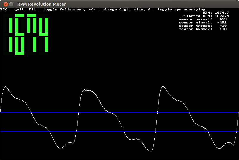
On important feature of the software is that it actually shows you the audio signal and the thresholds used for calculating revolutions. I would not trust a revolution meter not providing that, since the responses you get can differ depending on what you are pointing at, and depending on which disturbances you have in your environment.
The software automatically adjusts its thresholds based on minimum and maximum amplitudes of the received audio signal, so within some second(s) you should have usable readings.
If you are looking at a fan or similar things (generating more than one peak per revolution), you can give a divisor as a flag to the program to get correct readings.
Since really slow movements won’t pass into the microphone input circuit of your computer, one can optionally set a minimum required amplitude before the software starts reporting revolutions. Otherwise the auto scaling of the thresholds would start reporting revolutions based on the input noise of your sound card.
I consider the rest to be documented by the README.md file in the source code, as well as by the unit tests :)
Useful software libraries
I use gstreamer as a mean to get hold of the audio samples. I really like that framework. One appealing aspect of it is that you don’t have to do everything programatically. Most of the magic happens in a concept called a pipeline. And it’s possible to prototype the pipelines as strings on the commandline. When you have the correct one that you want to use, you typically would want to hook yourself into the pipeline in either the source side or the sink side. Doing that is quite easy using either of two pipeline elements called the appsrc and the appsink.
For the GUI part, I’m most often using SDL. I’m still using SDL 1.2. It does everything I need today, and I don’t feel any urgent need to learn the 2.0 framework. Now and then I consider committing to learn gtk or qt. I’ve experimented with both, and lean slightly more toward gtk, but have not done anything large with either of them.