The Walking Cube
1. Background
This is a writeup of a project which I and an old colleague of mine built a few years ago. I would say that I probably was the main reason that we tried this, but Strömbom was definitely the main reason we could build it (access to a machine shop, great at CAD (both mechanics and electronics), and with a library of source code from slightly related projects).
I would consider it a proof of concept which we learned a lot from. It did prove the concept, but not in such a dramatic way we would have preferred it to.
2. Goal
The goal was that the cube should turn over from one side to another side in a smooth manner, and with a mechanism that could be extended to make a smoothly walking triangle. If taken to the extremes, it would be possible to make a rectangular box using these principles that would even be able to climb stairs!
3. Table of contents
- 1. Background
- 2. Goal
- 3. Table of contents
- 4. What it is
- 5. What it does
- 6. Mechanics
- 7 Electronics
- 8. Miscellaneous notes
- 9. Patch instruction digital PCB
- 10. Source code
- 11. Links
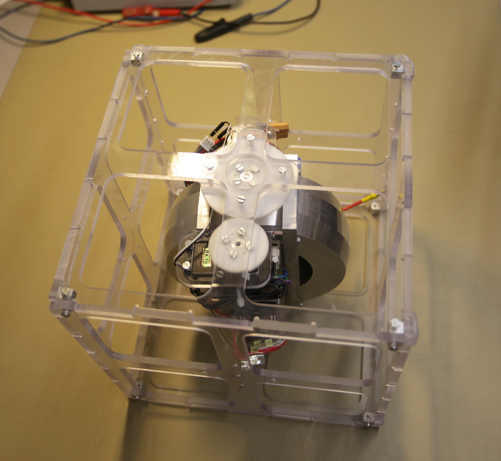
4. What it is
The inwards is basically a flywheel whose orientation can be changed by a servo. The idea was to exploit the gyroscopic forces:
If you hold the axis of a rotating flywheel, and apply a turning torque perpendicular to the rotation axis of the flywheel, you will end up with a torque perpendicular to both the originally applied torque and the axis of the flywheel.
One problem we knew we were going to get was an effect called precession, which basically is the effect that causes a spinning top to twirl faster and faster as it slows down. In our cube, we thought that if we were spinning the flywheel fast enough and could apply our torque to flip the cube over fast enough, we could disregard the precession effect (but it wasn’t as easy as we thought).
A better alternative to combat the precession might have been to have two servos for rotating the flywheel, so we could apply or external torque to the flywheel in any direction we wanted, to get more control over how the cube would flip. We didn’t go for a two servo solution to arbitrarily turn the flywheel, since that would have made it more complicated, and would have increased the weight of the cube as well.
Another solution might have been to mount two flywheels perpendicular to each other, but I have not done the math to show that it would work (and my intuition in these parts of mechanics is not that good).
5. What it does
The cube vibrates, makes loud noises, and proves that it’s possible to use “gyroscopic forces” to flip a cube over. It does however not really walk, although it’s able to take at least one step.
6. Mechanics
There are two main structural components: The outer polycarbonate shell, and an inner mount holding both PCB:s as well as the flywheel, motor, and a servo.
6.1 Designing the flywheel
The flywheel was machined out of aluminum, mostly because it was easy to get hold of, and would be easy to machine. That choice of material is not optimal in the sense that we want the flywheel to weigh as much as possible in comparison to the rest of the cube. We’ve made the flywheel thicker in the outer part, since the part closer to the center will contribute with less angular momentum, and would basically only weight down the cube without contributing much to gyroscopic effects.
To determine how much to carve out in the center of the flywheel, we did some simulations. We basically assumed that we would successfully flip the cube over if the angular momentum of the spinning flywheel would be less then one tenth of the precession’s maximum angular momentum when integrating up all the effects of precession during a step of the cube. (A step for the cube would be a 90 degree rotation). We also assumed certain dimensions and weights, as well as the time needed to take a step. The results of those simulations was graphs like this one for a cube with a side length of 15cm:
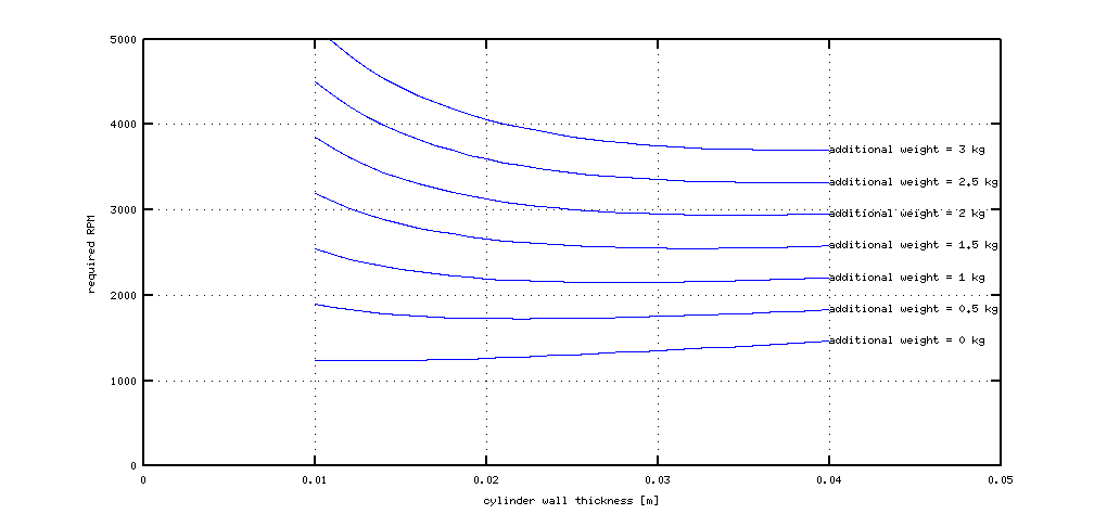
Based on those assumptions and the simulations, we let the outermost 3 cm of the flywheel have full depth, and carved out the innermost part of the flywheel. It turned out that most of our assumptions was wrong:
- Most things got slightly bigger and heavier than expected
- The torque of the servo wasn’t enough to flip the cube over fast enough
- The output torque of the “gyroscopic force” caused the cube to often support the weight of itself in just one corner, causing the cube to rotate freely on the ground (due to precession).
We did run the same simulations for a triangle as well. If the assumptions would have been valid, you would have needed roughly twice the spinning speed on the same flywheel to be able to flip over a triangle (with side lengths 31cm) instead of flipping over a cube (with side lengths 15cm).
6.2 Inner frame
The function of the inner frame is to provide mounting of of the flywheel, the motor, a servo, as well as batteries and miscellaneous PCB:s. In this prototype, the inner frame is connected to the outer shell using ball bearings, so the inner frame can rotate freely inside the outer shell. A servo with cog wheels mounted on the inner frame mates with a cog wheel which is fixed on the outer frame, to be able to provide a torque acting on the flywheel.
6.3 Shaft, motor, and motor mount
We didn’t intend to run this experiment for a long time, so instead of using a flexible coupling between the motor and the shaft, we just used a rigid shaft. It’s quite likely that we actually bent the shaft slightly when we press fitted it into the flywheel (using a vise). We noticed that because the ball bearings locked up slightly depending on how the flywheel was rotated. We solved that in an easy but non-optimal way by swapping out the regular ball bearings with self aligning ball bearings.
The brushless DC motor is mounted elevated from the side of the inner frame, mainly to facilitate assembly. That also makes the mounting of the motor less rigid, which could be good if you have a slightly bent shaft. The opposite end of the shaft has a magnet, which is used to read the absolute angle of the shaft. The shaft angle is then used by the software which controls the motor driver to determine which windings to energize.
6.4 Outer shell
I was heavily impressed that Strömbom managed to design the side pieces of the cube in such a way that the same mill file was used for milling out all six sides of the cube. I wasn’t even sure that that was possible.
The cut outs in the side pieces was originally intended to be pocket milled (to reduce weight). But the finish didn’t turn out that nice, so we changed from pockets to cut outs.
The small cubes in the corners are threaded, and holds together all sides of the cubes.
7 Electronics
The electronics is split into two different boards. One digital board, and one driver board.
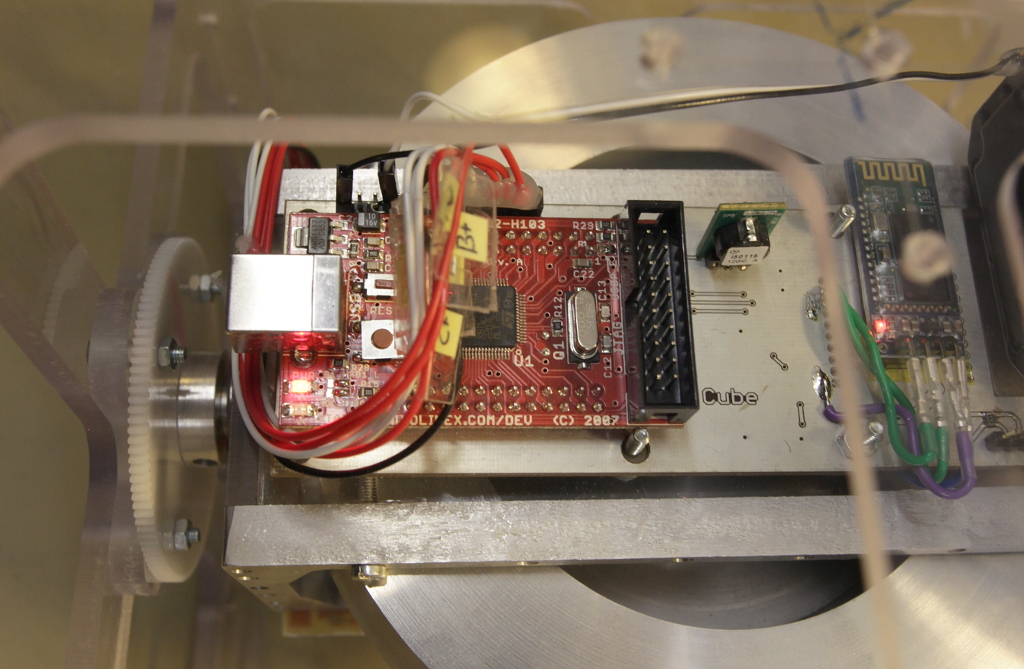
7.1 Digital board
The software on the digital board runs on a Cortex-M3 module from Olimex (STM32-H103). The software is responsible for three things:
- wireless communication
- controlling the servo that rotates the flywheel inside the outer shell
- controlling the brushless motor
7.1.1 Wireless communication
In the beginning, we had decided to use an Xbee module, but we repeatedly had issues with it, and we really don’t know why. Could have been interference with wlan networks or something else. We ended up using a bluetooth module I had gotten from ebay instead. The bluetooth module extends the serial port of the Cortex-M3, and makes it possible to send settings to the cube, and to receive telemetry back. We wrote a simple android app which uses bluetooth for controlling the cube.
7.1.2 Controlling the servo that rotates the flywheel inside the outer shell
The servo used for rotating the flywheel inside the outer shell was a Dynamixel RX-10 servo. That servo happens to speak RS485, so the digital board have an RS485 driver for it as well.
During early prototyping, I made the most stupid simple driver for RS485 using an arduino board: Just polling the RX pin in the main loop and set two outputs depending on input (one to the value of the RX pin, and one to the inverse of that). That actually worked out really well if anybody needs to bodge together an RS485 converter. You may have to disable interrupts if your communication speed is higher then ours though.
7.1.3 Controlling the brushless motor
It turns out that it’s not trivial to drive brushless DC motors connected to large masses, so we actually used our own driver, together with a sensor used for reading the angular position of the main shaft.
Sensorless brushless DC motor controllers need a spinning motor to be able to sense the position of the output shaft (by back EMF voltage readings), so it can determine when to excite which windings. Most hobby level controllers (for RC models) manage by using a predefined start sequence. It’s only if the motor manage to spin up during that start sequence that the controller would have any chance of controlling the motor. Otherwise it would end up driving the coils out of sync with the mechanical angle of the motor, typically resulting in no torque at all.
Our solution used a magnet placed on the end of the flywheel axis, and a chip (AS5134) that sensed that magnetic field, and made it possible to read out the absolute position (in degrees) of the axis. We then used software to determine which motor coils to energize.
One can read more about brushless DC motor control in Microchips application note “Brushless DC Motor Control Made Easy”.
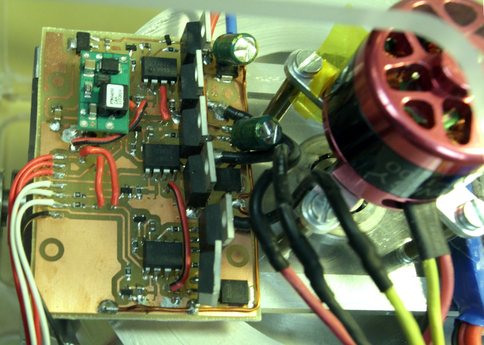
7.2 Motor driver board
The driver board is powering the brushless DC motor. The board have one mosfet half-bridge for each of the three phases. Each half bridge have a FAN73832 half bridge gate-drive IC, which in turn controls some fairly high current rated mosfets (FDP040N06).
Each of the three channels on the motor driver board looks like this:
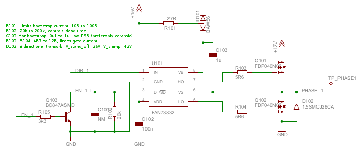
The strangely placed diode D102 is actually a bidirectional transient suppressor, protecting both mosfets. We didn’t care creating a custom symbol for it in eagle. D102 should not be needed if we could guarantee that the +12V voltage to the bridge would not blow up or become disconnected.
The PCB itself ended up as a single layer board with a minimal number of jumpers, and we designed it “mirrored”, to avoid having to drill any holes.
We had a few problems with the motor driver in the beginning. The first was that we thought it would be enough to drive it with a 1000mAh LiPo battery pack, but it turned out that it would drain that battery way faster then expected, so we started driving the motor using a regular power supply instead.
Our second problem was that we actually managed to burn off one of the traces on the motor driver PCB. After that, we reinforced all high current paths using reasonably sized solid copper wires. I don’t know if it was needed, but I added “kinks” to the copper wires, so any length extension due to heat would have somewhere to go instead of potentially bending the circuit board.
Another problem might have been caused by caution. I’m a big fan of passive safety, and thought it would be a good idea to have a small piece of resistance wire in series with the battery, so we wouldn’t end up short-circuiting the LiPo battery pack while we were testing the driver board and implementing the motor driver software. That may have meant that that the voltage to the driver board could dip, so we wouldn’t drive the mosfets properly (they did get hotter then anticipated, considering that RDSon was specified to be 4 mOhm @Igs=10V and Id=75A). Another possibility for hot mosfets could have been that our PWM-frequency was fairly high. If your RDSon is small enough, you end up only heating your mosfet every time they transition, since they only will have both higher resistance and higher current during the transitions.
The last problem we had in the beginning (when we only had a 13.8V power supply that could deliver enough current) was that the engine would end up dramatically hot. My theory is that we actually started to saturate the iron in the motor, resulting in large hysteresis losses.
Recently, I got a new power supply, so I have been able to run the motor at lower voltages. Now the motor won’t get close to those temperatures again. That suggests that it could not have been heating from eddy currents only (I would have expected a more linear relationship in that case).
8. Miscellaneous notes
One of the most important things to remember is that a flywheel actually stores a large amount of energy, so you should really make sure that it’s contained.
I had to hot glue two ball bearings in place to avoid that the inner frame was forced loose when trying to get the cube walking. The forces acting on the system is actually quite large.
9. Patch instruction digital PCB
We had forgotten to route some lines, so we had to mod the board to get it working. We did learn one thing though: If you are pouring a ground plane and won’t be using a solder mask, add a larger margin to conductors than we did. It was slightly tricky to solder :)

10. Source code
Most of the source code and cad drawings are available at http://cubewalker.googlecode.com
11. Links
- Youtube lecture talking about gyroscopes: Lecture 24: Rolling Motion, Gyroscopes in 8.01 Classical Mechanics (Walter Lewin)
- Microchip, Application note 857: Brushless DC Motor Control Made Easy
- Precession of Spinning Top: Precession of Spinning Top